Next: Examples and comparisons Up: Model description Previous: Installation Contents
| Title | |
| Source | Block |
| Altimetry | Block |
| Sound Speed | Block |
| Objects | Block |
| Bathymetry | Block |
| Array | Block |
| Output | Block |
The Title is a character string, which is written in the LOGFIL (the file with the *.log extension).
The structure of each block is as follows:
| ds | ray step |
| rx,zx | source coordinates |
| rbox(1),rbox(2) | range box |
| freqx | source frequency |
| nthtas | number of launching angles |
| theta(1), theta(nthtas) | first and last launching angles |
| atype | surface type |
| aptype | surface properties |
| aitype | interpolation type |
| atiu | attenuation units |
| nati | number of surface coordinates |
atype can be one of the following characters:
| 'A' | absorbent surface |
| 'E' | elastic surface |
| 'R' | rigid surface |
| 'V' | vacuum over surface |
aptype can be one of the following characters:
| 'H' | homogeneous surface |
| 'N' | non-homogeneous surface |
aitype can be one of the following strings:
| 'FL' | flat surface |
| 'SL' | surface with a slope |
| '2P' | piecewise linear interpolation |
| '3P' | piecewise parabolic interpolation |
| '4P' | piecewise cubic interpolation |
atiu can be one of the following characters:
| 'F' | dB/kHz |
| 'M' | dB/meter |
| 'N' | dB/neper |
| 'Q' | Q factor |
| 'W' | dB/ |
nati is the number of surafce coordinates.
For aptype = 'H' the properties and coordinates of the surface are specified as follows:
| rati(1),zati(1) |
| rati(2),zati(2) |
| rati(3),zati(3) |
| ... |
| rati(nati),zati(nati) |
| rati(1),zati(1),cpati(1),csati(1),rhoati(1),apati(1),asati(1) |
| rati(2),zati(2),cpati(2),csati(2),rhoati(2),apati(2),asati(2) |
| rati(3),zati(3),cpati(3),csati(3),rhoati(3),apati(3),asati(3) |
| ... |
| rati(nati),zati(nati),cpati(nati),... |
| cdist | type of sound speed distribution |
| cclass | class of sound speed |
| nr0,nz0 | number or points in range, number of points in depth |
| 'c(z,z)' | sound speed profile | |
| 'c(r,z)' | sound speed field |
| 'ISOV' | isovelocity | profile |
| 'LINP' | linear | profile |
| 'PARP' | parabolic | profile |
| 'EXPP' | exponential | profile |
| 'N2LP' | profile | |
| 'ISQP' | inverse-square gradient | profile |
| 'MUNK' | Munk | profile |
| 'TABL' | tabulated | profile |
| z0(1),c0(1) |
| z0(2),c0(2) |
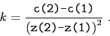
![\begin{displaymath}k = \frac {1}{ \makebox{\texttt{z(2)-z(1)}} }\ln\left[ \frac ...
...ebox{\texttt{c(1)}} }{ \makebox{ \texttt{c(2)} } } \right] . \end{displaymath}](img312.png)
![\begin{displaymath}\frac{dc}{dz} = \frac {-kc_0}{2\left[ 1+k\left( z-z_0 \right)...
... {3k^2c_0}{4\left[ 1+k\left( z-z_0 \right) \right] ^{5/2}} ; \end{displaymath}](img314.png)
![\begin{displaymath}k = \frac {1}{ \makebox{\texttt{z(2)-z(1)}} }\left[ \left( \f...
...tt{c(1)}}}{\makebox{\texttt{c(2)}}} \right) ^2 - 1 \right] . \end{displaymath}](img315.png)
![\begin{displaymath}c(z) = c_0 \left\{ 1 + \frac {k\left( z - z_0 \right) }{ \left[ 1 + k^2\left( z - z_0 \right) ^2 \right] ^{1/2} } \right\} , \end{displaymath}](img316.png)
![\begin{displaymath}
\frac{dc}{dz} = \frac {kc_0}{2\left[ 1+k^2\left( z-z_0 \righ...
...ht) }{\left[ 1+k^2\left( z-z_0 \right) ^2 \right] ^{5/2}} ;
\end{displaymath}](img317.png)
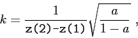
![\begin{displaymath}a = \left[ \frac {\makebox{\texttt{c(1)}}}{\makebox{\texttt{c(2)}}} - 1 \right] ^2 . \end{displaymath}](img319.png)
| z0(1),c0(1) |
| z0(2),c0(2) |
| ... |
| z0(nz0),c0(nz0) |
| r0(1),r0(2),r0(3),...,r0(nr0) |
| z0(1),z0(2),z0(3),...,z0(nz0) |
| c(1,1) c(1,2) ... c(1,nr0) |
| c(2,1) c(2,2) ... c(2,nr0) |
| c(3,1) c(3,2) ... c(3,nr0) |
| ... |
| c(nz0,1) c(nz0,2) ... c(nz0,nr0) |
After the Sound Speed Block it should follow the single line
| otype | object type |
| obju | attenuation units |
| no | number of coordinates |
| ocp(i), ocs(i), orho(i) ... | Object |
| ro(1),zdn(1),zup(1) | |
| ro(2),zdn(2),zup(2) | |
| ... | |
| ro(no),zdn(no),zup(no) |
Bathymetry Block: the structure of this block is identical to the structure of the Altimetry Block.
| artype | array type |
| nra nza | number of hydrophones along range and depth |
| r(1) r(2) .... r(nra) | hydrophones ranges |
| z(1) z(2) .... z(nza) | hydrophones depths |
| 'RRY' | Rectangular | aRray |
| 'HRY' | Horizontal | arRay |
| 'VRY' | Vertical | arRay |
| 'LRY' | Linear | arRay |
| outype | output type |
| miss | eigenray parameter |
The option outype defines the type of output and can correspond to one of the following strings:
| 'RCO' | output Ray COordinates; |
| 'ARI' | output All Ray information; |
| 'ERF' | output Eigenrays (use Regula Falsi); |
| 'EPR' | output Eigenrays (use PRoximity method); |
| 'ADR' | output Amplitudes and Delays (use Regula falsi); |
| 'ADP' | output Amplitudes and Delays (use Proximity method); |
| 'CPR' | output Coherent acoustic PRessure; |
| 'CTL' | output Coherent Transmission Loss; |
| 'PVL' | output coherent Particle VeLocity; |
| 'PAV' | output Coherent acoustic Pressure And Particle velocity. |
The miss parameter is used as a threshold to find eigenrays and to calculate arrivals.
Orlando Camargo Rodríguez 2012-06-21