CINTAL logo

AOB - an easily deployable and reconfigurable multifunctional acoustic-oceanographic system

Cintal logo
  A. Silva, F. Zabel, C. Martins and S.M. Jesus
SiPLAB - FCT, University of Algarve, Campus de Gambelas, 8005-139 Faro, Portugal
tel: +351-289800949 - fax: +351-289864258
 www.ualg.pt/siplab/ e-mail: sjesus@ualg.pt


Funded by CINTAL - University of Algarve under projects NUACE (POSI/CPS/47824/2002) and RADAR (POCTI/CTA/47719/2002) from Foundation for Science and Technology (FCT)

1. The AOB system concept

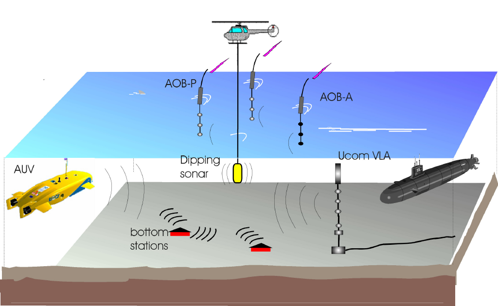
The Acoustic-Oceanographic Buoy (AOB) system is composed of a number of individual free drifting buoys and a set of monitoring and distributed processing applications on  local and remote platforms. A vision of the AOB - system is sketched in the picture below, together with some possible applications.

AOB system typical scenario


Image: AOB system composed of three AOBs, two passive (listening only) and one active (listening and emitting).  AOBs are free drifting GPS located, self recording and at all time monitored via a wireless lan network. Represented applications include: global underwater positioning/tracking of cooperating platforms (such as AUVs), coherent underwater communications with subs, AUVs, bottom stations or shore linked hubs, rapid environmental assessment via full field inversion of both water column and bottom properties for prediction systems initialization and active/passive source detection, classification and localization.


2. AOB development phases

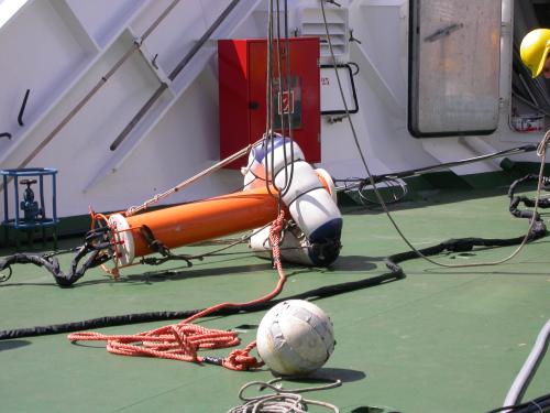
The first AOB prototype was developed in the first semester of 2003 during project LOCAPASS and tested at sea during the MREA'03 aboard the R/V Alliance in June 2003, off the coast of Italy. The LOCAPASS project description can be found here , the MREA'03 sea trial is here and results were published in [1 , 2 , 3 ] . That first version was based on a embeded PC architecture running NTe, with 4 hydrophones and no thermistors. The body of the surface buoy (represented on the figure on the right while being recovered during the MREA'03 ) was relatively large and heavy. Autonomy was approximately 6 hours.

AOB1


AOB1 aboard R/V Alliance (MREA, April 2004): a few modifications were introduced in 2004: a new array was built with 8 Sensor Tech wideband hydrophones, a water ON/OFF switch was implemented and a self recording thermistor chain from RBR was also colocated  with the acoustic array. This first AOB modified system was tested in April 2004 during the MREA'04 sea trial, off the coast of Portugal, always aboard the R/V Alliance.
.


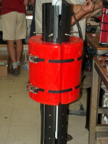
AOB2 aboard the R/V Kilo Moana being prepared for deployment. The second version of the AOB, developed between Aug04 and Aug05, adopted a radically diferent approach for the buoy electronics: the PISAbackplane embedded PC was replaced by a PC104+ based system incorporating a CPU, a GPS, a timer, wireless, a DAQ board and a DSP. The  surface buoy  is built in double aluminium container (one for batteries and one for the electronics) protected by nylon rubber plates. The batteries are Li-Ion packs with a much higher energy/weight ratio that give a lighter buoy with a higher autonomy. The system is running Linux and is monitored via a wireless lan network from a base station (directional antenas). This second AOB version (AOB2) is being tested during the Makay Experiment, aboard the R/V Kilo Moana off the Island of Kauai in Hawaii (US). This test was made possible via the ongoing collaboration of SiPLAB / UALg under High Frequency Initiative (HFi) project under the coordination of Mike Porter (HLS Research).
AOB2 aboard R/V Kilo Moana


Last update : 16 September 2005